
Welcome back! Today, we’ll learn how to use a button to control an LED in different ways. But first, we’ll start with something simple: toggling an LED on and off with a button.
The hardware setup remains the same as in Part 1, with the LED connected to GPIO4 and the button to GPIO2, See part 1.
Task 1: Toggle the LED with a Button (Without Fixing Bounce Issues)
How Does It Work?
The program continuously checks the button state.
- If the button transitions from unpressed to pressed, the LED toggles its state.
- The
last_button_stateensures the program only toggles the LED once per press. - The
vTaskDelayprevents rapid polling and keeps the system efficient.
The Program Checks the Button Continuously
The program runs in a loop that keeps checking if the button is pressed. This way, it always knows the current state of the button.
Detecting When the Button is Pressed
When the button goes from “not pressed” to “pressed” (a transition called the falling edge), the program knows it’s time to take action. This ensures the program responds only to actual presses.
Toggling the LED’s State
If the button is pressed, the program changes the LED’s state. Each press toggles the LED.
Making Sure It Toggles Only Once per Press
The program uses a variable, last_button_state, to remember the button’s previous state. This helps the program know whether the button is pressed for the first time or is still being held down. As a result, the LED toggles only once, no matter how long you hold the button.
Using a Small Delay for Efficiency
A tiny pause (using vTaskDelay) is added between checks. This prevents the program from constantly checking the button without rest, which could waste resources. Additionally, this delay ensures smooth and predictable operation.
Here’s the Code
First, we’ll write code to toggle the LED state each time you press the button.
#include <stdio.h>
#include "driver/gpio.h"

// Define GPIO pins
#define LED_PIN GPIO_NUM_2
#define BUTTON_PIN GPIO_NUM_0

// Variables to track the button state
int led_state = 0;
int last_button_state = 1; // Assume unpressed at the start

void app_main() {
    // Configure LED as output
    gpio_reset_pin(LED_PIN);
    gpio_set_direction(LED_PIN, GPIO_MODE_OUTPUT);

    // Configure button as input
    gpio_reset_pin(BUTTON_PIN);
    gpio_set_direction(BUTTON_PIN, GPIO_MODE_INPUT);

    while (1) {
        // Read the current state of the button
        int button_state = gpio_get_level(BUTTON_PIN);

        // Check if the button has been pressed (falling edge)
        if (last_button_state == 1 && button_state == 0) {
            led_state = !led_state; // Toggle the LED state
            gpio_set_level(LED_PIN, led_state); // Update LED
        }

        // Update the last button state
        last_button_state = button_state;

        // Small delay to reduce CPU usage
        vTaskDelay(10 / portTICK_PERIOD_MS);
    }
}Code Explanation
Headers
#include <stdio.h> – Includes the standard input/output library. It provides basic functions like printing debug messages to the console.
#include "driver/gpio.h" – Includes the GPIO driver library. This library gives access to functions for configuring and using GPIO pins.
Variables
#define LED_PIN GPIO_NUM_2 – Defines LED_PIN as GPIO2, where the LED is connected. This makes it easier to reference this pin in the code.
#define BUTTON_PIN GPIO_NUM_0 – Defines BUTTON_PIN as GPIO0, where the button is connected. Like the LED pin, this makes the code easier to read and maintain
int led_state = 0; – Initializes led_state to 0, which means the LED is OFF at the beginning. This variable tracks whether the LED is ON or OFF.
int last_button_state = 1; – Initializes last_button_state to 1, assuming the button is not pressed at the start. This helps detect when the button is pressed later.
Loop
void app_main() – The main function where the program runs. This is the entry point for ESP-IDF applications.
gpio_reset_pin(LED_PIN); – Resets the configuration for the LED pin, ensuring it’s cleanly set up for use.
gpio_set_direction(LED_PIN, GPIO_MODE_OUTPUT); – Configures the LED pin as an output, allowing the program to control it (turn it ON or OFF).
gpio_reset_pin(BUTTON_PIN); – Resets the configuration for the button pin, ensuring it’s cleanly set up for use.
gpio_set_direction(BUTTON_PIN, GPIO_MODE_INPUT); – Configures the button pin as an input, so the program can read its state (pressed or not).
while (1) – Creates an infinite loop, ensuring the program keeps running and checking the button state continuously.
int button_state = gpio_get_level(BUTTON_PIN); – Reads the current state of the button pin. It will be 0 if the button is pressed (active LOW) or 1 if not pressed.
if (last_button_state == 1 && button_state == 0) – Checks if the button state has changed from 1 (not pressed) to 0 (pressed). This is called detecting the falling edge.
led_state = !led_state; – Toggles the LED state. If led_state was 0 (OFF), it becomes 1 (ON), and vice versa.
gpio_set_level(LED_PIN, led_state); – Updates the LED’s pin with the new state, turning it ON or OFF based on led_state.
last_button_state = button_state; – Updates last_button_state to match the current button_state. This ensures the program can detect changes in the button state during the next loop iteration.
vTaskDelay(10 / portTICK_PERIOD_MS); – Pauses the program for 10 milliseconds. This reduces CPU usage and ensures smooth polling of the button state.
Does it Work?
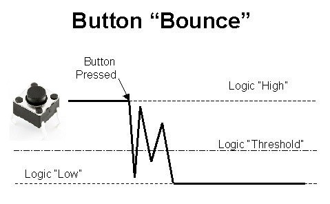
Give it a try! Does the LED toggle as expected? Most likely, it doesn’t. In fact, it might toggle twice with a single press. This issue arises due to button bounce—a rapid flickering of the button signal when pressed. Consequently, the program misinterprets multiple presses. Therefore, let’s address and fix this issue in the next step!
Task 2: Fixing Button Bounce
To fix the bounce, we’ll use a delay to ignore the extra flickers. Here’s the improved code:
#include <stdio.h>
#include "driver/gpio.h"

// Define GPIO pins

#define LED_PIN GPIO_NUM_4 // GPIO pin where the LED is connected
#define BUTTON_PIN GPIO_NUM_2 // GPIO pin where the button is connected

// Variables

int led_state = 0; // Tracks the current state of the LED
int last_button_state = 1; // Stores the last state of the button

int debounce_delay = 50; // Debounce delay in milliseconds

unsigned long last_debounce_time = 0; // Timestamp of the last detected state change

void app_main() {

    // Reset and configure the LED pin as output
    gpio_reset_pin(LED_PIN);
    gpio_set_direction(LED_PIN, GPIO_MODE_OUTPUT);

    // Reset and configure the button pin as input
    gpio_reset_pin(BUTTON_PIN);
    gpio_set_direction(BUTTON_PIN, GPIO_MODE_INPUT);

    // Infinite loop to continuously check button state
    while (1) {

        // Read the current state of the button
        int button_state = gpio_get_level(BUTTON_PIN);

        // Check if the button state has changed from the last loop
        if (button_state != last_button_state) {
            // Update the debounce timer with the current time in milliseconds
            last_debounce_time = esp_timer_get_time() / 1000;
        }

        // Check if the button state has remained stable beyond the debounce
        //delay
        if ((esp_timer_get_time() / 1000 - last_debounce_time) > debounce_delay) {

            // If the stable state is "pressed" (LOW), toggle the LED
            if (button_state == 0) {
                led_state = !led_state; // Change the LED state
                gpio_set_level(LED_PIN, led_state); // Update the LED

            }
        }

        // Update the last button state for the next iteration
        last_button_state = button_state;

        // Add a short delay to reduce CPU usage and allow stable polling
        vTaskDelay(10 / portTICK_PERIOD_MS);
    }
}How This FixWorks
- When the button state changes, the program notes the time in
last_debounce_time. - The program waits until the state remains stable for longer than the
debounce_delay(50ms). - Then check the button state, If the stable state is pressed (LOW), the LED toggles ON or OFF.
This process avoids multiple toggles caused by the rapid flickers of button bounce.
Code Explanation
Variable Declarations for Debouncing
int debounce_delay = 50; – This sets a 50-millisecond delay for debounce. It ensures the button’s state must remain stable for at least 50ms before the program considers it valid. This filters out the quick flickers (bounces) that occur when the button is pressed or released.
unsigned long last_debounce_time = 0; – This variable stores the last time (in milliseconds) when the button state changed. It helps calculate how long the button state has remained stable. We don’t use a timer or delay for that.
Detecting a Change in Button State
if (button_state != last_button_state) – Compares the current button state (button_state) with the previous state (last_button_state). If they are different, it means the button state has changed (e.g., pressed or released).
last_debounce_time = esp_timer_get_time() / 1000; – This updates last_debounce_time with the current time (in milliseconds). The esp_timer_get_time() function provides the current time in microseconds, so it is divided by 1000 to convert it to milliseconds.
Checking for a Stable State
esp_timer_get_time() / 1000 - last_debounce_time – Calculates how much time has passed since the button’s state last changed. If the button’s state has remained stable (unchanged) for longer than the debounce_delay (50ms), it is considered valid.
if ((...) > debounce_delay) – This ensures the button state is stable and not bouncing. Only after the state is stable does the program respond (e.g., toggling the LED).
Adding Debounce to LED Toggle
if (button_state == 0) – Checks if the stable state is pressed (LOW). Only then does it toggle the LED.
led_state = !led_state; – Toggles the LED’s state:
- If the LED is OFF (
led_state = 0), it switches ON (led_state = 1). - If the LED is ON, it switches OFF
gpio_set_level(LED_PIN, led_state); – Updates the LED’s pin to match the new led_state. The LED turns ON or OFF depending on the state.
Homework Introduction
Now that you’ve learned how to handle GPIO inputs and control an LED, it’s time to put your knowledge to the test! Your homework challenges will help you apply these concepts creatively and solidify your understanding.
Try to complete the tasks on your own first—it’s the best way to learn and build confidence. Don’t worry if you get stuck; the solutions are provided below, but give it your best shot before peeking!
Home Task 1: LED Blinking Control
For your first task, make the button control LED blinking. When pressed:
- The first press makes the LED blink.
- The second press turns the LED off.
Try coding this yourself! However, if you’re stuck, the answer is provided below.
#include <stdio.h>
#include "driver/gpio.h"

// Define GPIO pins
#define LED_PIN GPIO_NUM_4 // GPIO pin connected to the LED
#define BUTTON_PIN GPIO_NUM_2 // GPIO pin connected to the button

// Variables
int led_blinking = 0; // Tracks whether the LED is blinking (1) or off (0)
int last_button_state = 1; // Stores the last state of the button
int debounce_delay = 50; // Debounce delay in milliseconds
unsigned long last_debounce_time = 0; // Timestamp of the last state change

void app_main() {
    // Configure LED as output
    gpio_reset_pin(LED_PIN);
    gpio_set_direction(LED_PIN, GPIO_MODE_OUTPUT);

    // Configure button as input
    gpio_reset_pin(BUTTON_PIN);
    gpio_set_direction(BUTTON_PIN, GPIO_MODE_INPUT);

    while (1) {
        // Read the current state of the button
        int button_state = gpio_get_level(BUTTON_PIN);

        // Check for state change
        if (button_state != last_button_state) {
            last_debounce_time = esp_timer_get_time() / 1000; // Update debounce timer
        }

        // Check if the state is stable for debounce delay
        if ((esp_timer_get_time() / 1000 - last_debounce_time) > debounce_delay) {
            if (button_state == 0) { // If the button is pressed
                led_blinking = !led_blinking; // Toggle the blinking state
            }
        }

        last_button_state = button_state; // Update the last button state

        // Handle LED blinking
        if (led_blinking) {
            gpio_set_level(LED_PIN, 1); // Turn LED on
            vTaskDelay(500 / portTICK_PERIOD_MS); // Wait 500 ms
            gpio_set_level(LED_PIN, 0); // Turn LED off
            vTaskDelay(500 / portTICK_PERIOD_MS); // Wait 500 ms
        } else {
            gpio_set_level(LED_PIN, 0); // Ensure LED remains off
        }

        vTaskDelay(10 / portTICK_PERIOD_MS); // Small delay for smooth polling
    }
}
Description of New Lines
int led_blinking = 0; – This variable tracks whether the LED is blinking or not.
0means the LED is OFF and not blinking.1means the LED is blinking.
led_blinking = !led_blinking; – Toggles the state of the led_blinking variable.
led_blinkingis0, it becomes1(start blinking).led_blinkingis1, it becomes0(stop blinking).
if (led_blinking) – Checks if led_blinking is 1. If true, the LED blinks by toggling ON and OFF with delays.
gpio_set_level(LED_PIN, 1); and gpio_set_level(LED_PIN, 0); – These lines control the LED:
1turns the LED ON.0turns the LED OFF.
vTaskDelay(500 / portTICK_PERIOD_MS); – Adds a delay of 500 milliseconds. This creates a blinking effect when paired with turning the LED ON and OFF.
else { gpio_set_level(LED_PIN, 0); } – Ensures the LED stays OFF when led_blinking is 0. This is important to avoid leaving the LED in an undefined state.
How It Works
This program has two separate tasks running within the same while loop:
- Debounce and Button Press Detection
- The first part of the loop checks the button state, applies debounce logic, and toggles the
led_blinkingvariable if the button is pressed.
- The first part of the loop checks the button state, applies debounce logic, and toggles the
- LED Control Based on Blinking State
- The second part of the loop handles the LED behavior. It either blinks the LED (if
led_blinkingis1) or keeps it OFF (ifled_blinkingis0).
- The second part of the loop handles the LED behavior. It either blinks the LED (if
Why This Approach Has Limitations
Running two tasks in the same loop can lead to timing issues, especially as the tasks become more complex:
- Impact on Button Responsiveness:
If the LED is blinking, the program spends time waiting duringvTaskDelay(500 / portTICK_PERIOD_MS). This delay can make the button press feel less responsive because the program cannot check the button state during these pauses. - Unpredictable Timing:
Since the button check and LED control share the same loop, their timing depends on each other. This coupling can cause problems in more advanced projects where precise timing is critical.
Suggested Improvement for Future Tasks
For better timing and responsiveness, consider separating these tasks:
- Use a Timer or Interrupt for Button Handling:
Instead of checking the button state in the main loop, use a timer or GPIO interrupt to handle button presses. This ensures the button is always responsive, regardless of what the rest of the program is doing. - Use a State Machine for LED Control:
Implement a state machine to manage the LED behavior independently of the button logic. This makes the program modular and easier to scale.
By understanding these limitations, you can plan for more complex projects and avoid potential timing issues as your programs grow!
Wrapping It Up
In this lesson, we learned how to use a button to control an LED on the ESP32. We fixed the button bounce problem and made the LED toggle, blink, and even change its blinking speed—all with just one button.
But, we also saw that doing many tasks in one loop can cause timing problems. As you work on bigger projects, try using interrupts or timers to keep everything running smoothly. These tools will help make your projects work faster and better.
To speed up your learning and dive deeper into embedded systems, check out our new MotionArc boards with step-by-step courses. These boards and lessons are designed to make learning faster and easier. Learn more and get started here: courses and boards.
Useful links
ESP32 Resources: Espressif Systems provides a comprehensive collection of resources, including datasheets, technical reference manuals, and application notes, offering in-depth information on ESP32’s GPIO capabilities.
ESP32 Product Page: The official product page offers an overview of the ESP32’s features, including its GPIO specifications, and links to additional documentation and resources.