
Why GPIO is So Cool
Welcome back! You’ve set up your ESP32 environment and got your first “Hello World” up and running, which is an important milestone. Now, it’s time to dive into something even more exciting—interacting with the real world using GPIO pins. GPIO (General Purpose Input/Output) is like giving your ESP32 “fingers” that can connect, control, and sense things. In this lesson, we’re going to blink an LED. It might sound simple, but blinking an LED is often the first step towards building things like automation systems, smart gadgets, and even full robotics projects. Let’s get ready to light things up!
When I first started playing with GPIO, the thrill of watching an LED blink in response to my code made all the hard work worth it. Suddenly, it wasn’t just software anymore—I could see something happening, right in front of me. Trust me, you’ll feel the same way. The satisfaction of seeing a little LED obey your command is one of those “ah-ha!” moments in embedded programming.
Hardware :
Quick Overview: Choosing Your Hardware Setup
Hardware plays a key role in any embedded project, just as important as software. There are multiple ways to set up your hardware—whether you use a breadboard, solder your circuit, work with a developer board, or design a custom PCB. Each method comes with its own advantages and challenges.
For a more detailed guide on these hardware approaches, including when to use each one, check out our dedicated post here: Read More About Hardware Options for Your Project.
This lesson is designed to work with any of these methods, so feel free to use the approach that best fits your needs!
But remember, your time is the most valuable resource you have.
1. Setting Up GPIO: A Practical Example “Hello World”
1.1 Create your hardware setup
For this lesson, we’re going to connect an LED light to our ESP32 board using one of its pins, called GPIO4. Think of GPIO4 as a finger that can turn the light on and off. We also need a small resistor 300-500 ohm to keep the LED safe and prevent it from getting too much power.
You should always use a resistor with an LED. A 330-ohm resistor is ideal for a 3.3V system like the ESP32.
We’ll connect the long leg of the LED to GPIO4, and the short leg through the resistor to a GND pin, that lets electricity flow.
It doesn’t matter which ESP32 board you have; any board will work.
If you still don’t have an LED or resistors or don’t know where to buy them or which ones to get, you can check out this article where I describe everything you need to get started with electronics.
Here is the schematic for this example:

or schematic for the breadboard:

1.2 Writing the Code to Control GPIO
Next, let’s write the code that makes the LED blink.
Open up Visual Studio Code and create a new project using the ESP-IDF extension. Let’s call this project “Blink_LED”.
Here’s the code to get the LED blinking:
#include <stdio.h>  // Standard input/output library for printing messages
#include "freertos/FreeRTOS.h"  // FreeRTOS library for task management
#include "freertos/task.h"  // FreeRTOS task library for delays
#include "driver/gpio.h"  // GPIO library to control input/output pins

#define BLINK_GPIO 4  // GPIO pin number where the LED is connected

void app_main(void)
{
    // Configure the GPIO pin as output
    gpio_pad_select_gpio(BLINK_GPIO);  // Select GPIO pin for use
    gpio_set_direction(BLINK_GPIO, GPIO_MODE_OUTPUT);  // Set the GPIO as an output pin

    while (1) {
        // Turn the LED on
        gpio_set_level(BLINK_GPIO, 1);  // Set GPIO level to HIGH (turn LED on)
        printf("LED is ON\n");  // Print status message to console
        vTaskDelay(1000 / portTICK_PERIOD_MS);  // Delay for 1 second

        // Turn the LED off
        gpio_set_level(BLINK_GPIO, 0);  // Set GPIO level to LOW (turn LED off)
        printf("LED is OFF\n");  // Print status message to console
        vTaskDelay(1000 / portTICK_PERIOD_MS);  // Delay for 1 second
    }
}
1.3 Code Explanation:
- Include Necessary Libraries:
#include <stdio.h>: This library allows us to use functions likeprintf()to print messages to the console.#include "freertos/FreeRTOS.h": This is the main FreeRTOS library that provides support for tasks and scheduling.#include "freertos/task.h": This library is used for task management, including delays (vTaskDelay).#include "driver/gpio.h": This library provides functions for GPIO configuration and control.
- Define GPIO Pin:
#define BLINK_GPIO 2: This line defines the GPIO pin number (GPIO 2) to which the LED is connected. Using a macro like this makes it easy to change the pin number later if needed.
- Configure GPIO Pin as Output:
gpio_pad_select_gpio(BLINK_GPIO): This function selects the GPIO pad for use, effectively enabling GPIO functionality for the specified pin.gpio_set_direction(BLINK_GPIO, GPIO_MODE_OUTPUT): This function sets the direction of the GPIO pin as output, which allows us to control the LED connected to it.
- Loop to Blink LED:
while (1): This creates an infinite loop that runs forever, repeatedly turning the LED on and off.gpio_set_level(BLINK_GPIO, 1): Sets the GPIO pin to a high level (3.3V), which turns the LED on.printf("LED is ON\n"): Prints a message to the console indicating that the LED is on.vTaskDelay(1000 / portTICK_PERIOD_MS): Causes a delay of 1000 milliseconds (1 second) before moving to the next instruction.gpio_set_level(BLINK_GPIO, 0): Sets the GPIO pin to a low level (0V), which turns the LED off.printf("LED is OFF\n"): Prints a message to the console indicating that the LED is off.vTaskDelay(1000 / portTICK_PERIOD_MS): Causes a delay of 1000 milliseconds (1 second) before repeating the loop.
1.4 Build, Flash, and Monitor
- Build the Code: In Visual Studio Code, click on the “Build” button in the ESP-IDF extension or use the command palette (
Ctrl+Shift+P), then typeESP-IDF: Build Your Project. This will compile your code. - Flash to ESP32: Make sure your ESP32 is connected to your computer via USB. In VS Code, click the “Flash” button in the ESP-IDF extension or use the command palette (
Ctrl+Shift+P), then typeESP-IDF: Flash Your Projectto upload the code to your ESP32. - Monitor Output: To view the output from the ESP32, use the command palette (
Ctrl+Shift+P), then typeESP-IDF: Monitor Your Project. You should see messages like “LED is ON” and “LED is OFF,” and your LED should be blinking accordingly.
2 Adding an Input Button Example
Now that you know how to make an LED blink, let’s add a button to control the LED.
In this example, we will control the LED by pressing and releasing the button. When the button is pressed, the LED will turn on, and when the button is released, the LED will turn off. This is a simpler example of basic button input.
2.1 Hardware Connections for Button
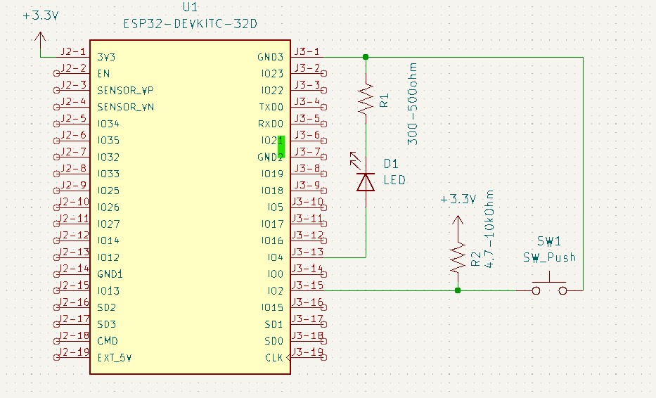
- Connect a push button to GPIO pin 2 on your ESP32. One side of the button should be connected to GPIO 2. It is also worth adding an external pull-up resistor to the GPIO, as the built-in ESP32 may be too weak. This means taking a 4.7-10k ohm resistor and connect one end to GPIO 2 and the button, and the other to +3.3V. You will see it on the schematic.
- The other side should be connected to the GND pin of your ESP32.
Here is the schematic for this example:
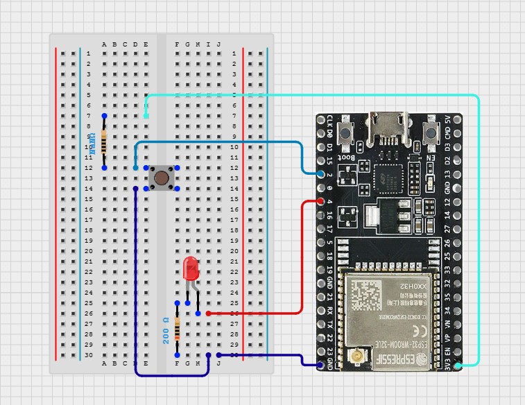
or schematic for the breadboard:
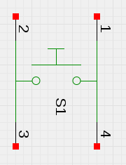
Note: The button has 4 pins, but it’s essentially 2 pairs of connected pins, making it easier to wire. When wiring, you can use either of the pins in a pair.
2.2 Writing the Code to Control LED with Button Press and Release
Here’s the code to make the LED respond to button press and release:
#include <stdio.h>  // Standard input/output library for printing messages
#include "freertos/FreeRTOS.h"  // FreeRTOS library for task management
#include "freertos/task.h"  // FreeRTOS task library for delays
#include "driver/gpio.h"  // GPIO library to control input/output pins

#define BLINK_GPIO 4  // GPIO pin number where the LED is connected
#define BUTTON_GPIO 2  // GPIO pin number where the button is connected

void app_main(void)
{
    // Configure the GPIO pin for LED as output
    gpio_pad_select_gpio(BLINK_GPIO);
    gpio_set_direction(BLINK_GPIO, GPIO_MODE_OUTPUT);

    // Configure the GPIO pin for Button as input
    gpio_pad_select_gpio(BUTTON_GPIO);
    gpio_set_direction(BUTTON_GPIO, GPIO_MODE_INPUT);

    while (1) {
        // Read the button state
        int button_state = gpio_get_level(BUTTON_GPIO);

        if (button_state == 1) {
            // If button is pressed, turn the LED on
            gpio_set_level(BLINK_GPIO, 1);
            printf("Button pressed, LED is ON
");
        } else {
            // If button is not pressed, turn the LED off
            gpio_set_level(BLINK_GPIO, 0);
            printf("Button not pressed, LED is OFF
");
        }

        vTaskDelay(10 / portTICK_PERIOD_MS);  // Small delay to debounce the button
    }
}2.3 Code Explanation:
The initial part of the code is identical to the first section, so its description is provided below in the hidden text. You can expand it for more details.
Include Necessary Libraries: ( You can open it )
#include <stdio.h>: This library allows us to use functions likeprintf()to print messages to the console.
#include "freertos/FreeRTOS.h": This is the main FreeRTOS library that provides support for tasks and scheduling.
#include "freertos/task.h": This library is used for task management, including delays (vTaskDelay).
#include "driver/gpio.h": This library provides functions for GPIO configuration and control.
Define and GPIO Pins ( You can open it )
#define BLINK_GPIO 2: Assign GPIO pin 4 to control the LED.
#define BUTTON_GPIO 4: Assigns GPIO pin 2 for the push button input.
Function app_main(): This function is the entry point of the application where the main tasks are performed.
Configure GPIO Pins: ( You can open it )
gpio_pad_select_gpio(BLINK_GPIO): Enables the GPIO functionality for GPIO pin 4.
gpio_set_direction(BLINK_GPIO, GPIO_MODE_OUTPUT): Sets GPIO pin 4 as an output to control the LED.
gpio_pad_select_gpio(BUTTON_GPIO): Enables GPIO functionality for GPIO pin 2.
gpio_set_direction(BUTTON_GPIO, GPIO_MODE_INPUT): Sets GPIO pin 2 as an input to read the button state.
Main Loop:
while (1): Creates an infinite loop that keeps running to continuously check the button state and toggle the LED.- Read Button State:
int button_state = gpio_get_level(BUTTON_GPIO): Reads the state of the button—if the button is pressed or not. gpio_get_level returns the state of the GPIO pin and saves it in the button_state variable.
- Control the LED:
if (button_state == 1): If the button is pressed (1), continue to the next function.gpio_set_level(BLINK_GPIO, 1): Sets GPIO pin 2 high, turning the LED on.printf("Button pressed, LED is ON\n"): Prints a message to the console indicating that the LED is on.else: Ifif (button_state == 1)is not executed becausebutton_stateis not equal to 1, the next functions will be executed.gpio_set_level(BLINK_GPIO, 0): Sets GPIO pin 2 low, turning the LED off.printf("Button not pressed, LED is OFF\n"): Prints a message to the console indicating that the LED is off.
- Debounce Handling:
vTaskDelay(10 / portTICK_PERIOD_MS): Adds a small delay of 10 ms to help debounce the button, preventing false readings due to mechanical bounce. Note that this is not the best way to do it. I will show a better method later.
2.4 Build, Flash, and Monitor
Build the Code: In Visual Studio Code, click on the “Build” button in the ESP-IDF extension or use the command palette (Ctrl+Shift+P), then type ESP-IDF: Build Your Project. This will compile your code.
Flash to ESP32: Make sure your ESP32 is connected to your computer via USB. In VS Code, click the “Flash” button in the ESP-IDF extension or use the command palette (Ctrl+Shift+P), then type ESP-IDF: Flash Your Project to upload the code to your ESP32.
Monitor Output: To view the output from the ESP32, use the command palette (Ctrl+Shift+P), then type ESP-IDF: Monitor Your Project. You should see messages like “Button pressed, LED is ON” and “Button not pressed, LED is OFF” and your LED should be blinking accordingly.
3 This Lesson is Complete
We’ve successfully wrapped up this lesson, where we learned to control an LED using GPIO and even added a button to enhance interactivity. But our journey with GPIO and buttons doesn’t end here. In the next lesson, we’ll dive deeper into GPIO, exploring more ways to use buttons and other input components. Stay tuned and keep experimenting!
If you have any questions or need further clarification, feel free to ask in the comments. We’re here to help!
External Links for This Lesson:
- ESP-IDF GPIO Guide – Official overview of GPIO capabilities with configuration and usage examples.
- ESP32 Technical Reference Manual – In-depth hardware details, including GPIO registers and configurations.
- ESP32 Datasheet – Specifications, pin configurations, and electrical characteristics.
- ESP-IDF Get Started Guide – Step-by-step instructions for setting up ESP-IDF and beginning development.